


 |
|
| 제품특징 | 제품사양 | 자료실 |
Description
The TERX detection system is used to measure x-ray spectra at Electron Beam Ion Sources in dependence
on the ionisation time and in dependence on the electron energy.
The system needs to be combined with an x-ray detector. An appropriate detector is listed as optional
equipment in the table at the end of this document.
It is possible to use a customer-specific detector if certain requirements are fulfilled,
see table of technical parameters.
Functional Principle
The TERX Detection System controls the source potential and trap cycle of the ion source.
The x-ray events are counted directly from the X-ray detector and sorted in a time or energy matrix.
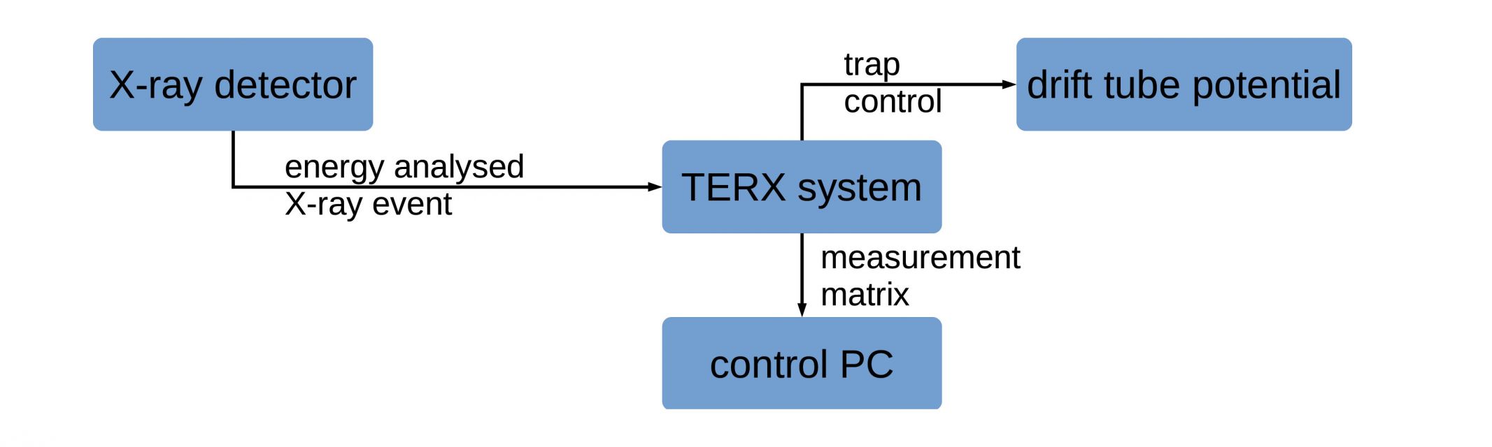
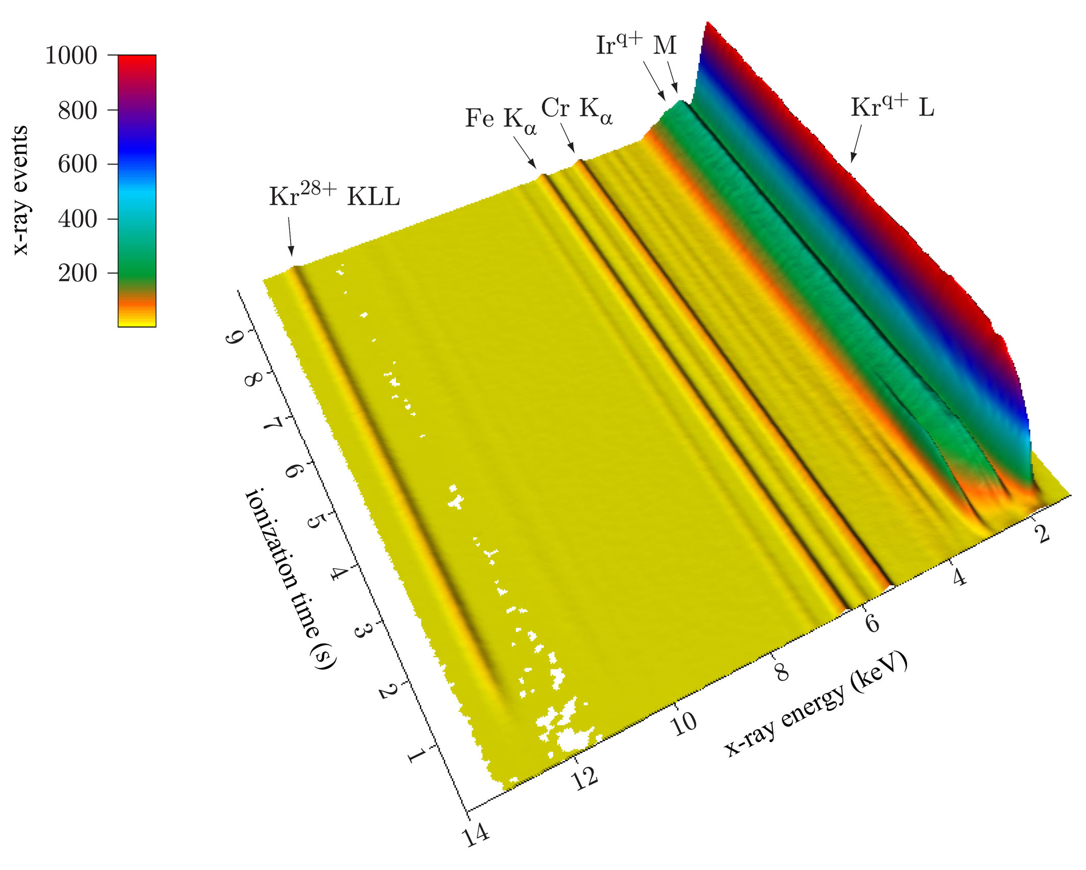
Figure 2 - time resolved measurement example
In time resolved measurement mode, the ion trap is controlled by the TERX system while
the x-ray detector analyzes the incoming x-ray events and gives the x-ray energy information
to a 12 pin output connector. The TERX system sorts the signal into a time-energy matrix.
This matrix is sent to the control PC.
A summary of the functional principle of this measurement mode is shown in Figure 1.
The minimum possible time resolution of the measurement system is 1 ms.
An example for a time resolved x-ray measurement is given in Figure 2.
The energy resolved x-ray measurement is done in a measurement loop, displayed in Figure 3.
The trap potential is set by the TERX system.
The trap potential is increased stepwise and in each measurement loop the X-ray events during
a trap cycle are stored and are labelled by the corresponding trap potential.
The minimal possible trap potential resolution depends on the accuracy of the drift tube potential unit.
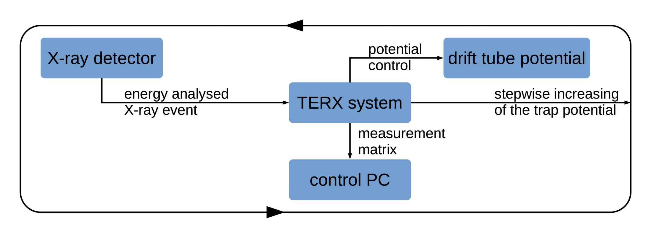
Figure 3 - electron beam energy resolved measurement scheme
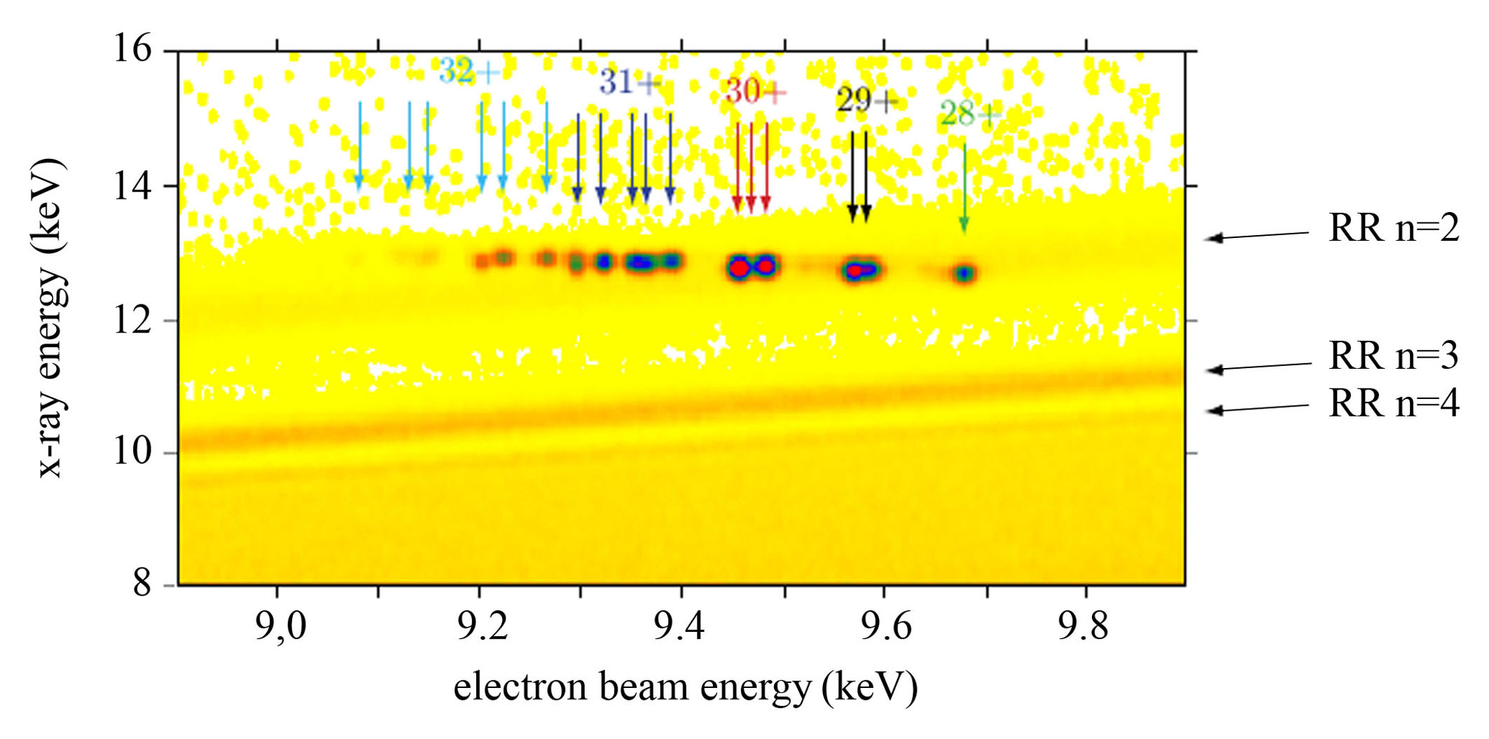
As an example for the (electron beam) energy resolved measurement mode, a measurement of the
dielectronic recombination (DR) and radiative recombination (RR) lines of Krypton ions is shown in Figure 4.
The data was recorded with the provided data acquisition software. With this software,
the data can be processed, used to create graphs, and saved for further applications.
| 제품특징 | 제품사양 | 자료실 |
Parameters
TERX System Parameters | |
minimum time resolution | 1 ms |
maximum x-ray detector resolution | 12 bit |
maximum electron beam energy resolution | 16 bit |
maximum count rate | 10000 cps |
Requirements for Detector Attachment | |
detector interface | signal type 5 V TTL |
output channels | 'Strobe' - incomming x-ray signal |
| 'High Load' - more x-ray signals arrive before first signal is read-out |
| 12 bit channel output of x-ray signals according to x-ray energy |
input channels | 'Clear 1' - clearing 'Strobe' and 12 bit x-ray output channels |
| 'Clear 2' - clearing the 'High Load' channel |
DOWNLOAD ProductSheet_TERX.pdf